Frequently asked questions / Troubleshooting
Dongle / License issues (6)
Since a license update can be applied to only one specific dongle, for an update of your licenses, we need a .C2V file which is created with your dongle. To do so, please visit http://localhost:1947 and select Sentinel Keys from the menu on the left. In case of multiple present dongles, select the dongle you want to update and click on the button C2V in the according entry. Download and send us the C2V file to contact@s649318252.online.de. To update your dongle, we will send you a .V2C file with the updated license information (see also How to activate/update your licence above).
Attach the dongle to one of the PCs in your network, start this PC, and make sure that port 1947 is released on all machines. Please also refer to section 1.2 of the thaTEC:OS user manual or contact us under contact@s649318252.online.de if the error persists.
Visit http://localhost:1947 to check whether Sentinel LDK is installed. If not, please run the thaTEC:Core installer again which can be found in our download section. If the error persists, please refer to section 2.2 of the thaTEC:OS user manual or contact us under contact@s649318252.online.de.
You can check and stop current sessions in your browser at http://localhost:1947.Licenses to some modules only allow a certain number of parallel executions. To prevent unnecessary waiting times, please makesure that all users stop the modules if they do not need them any more. For more information, please have a look at Section 2.1 of the thaTEC:OS user manual. Remark: Even though thaTEC:OS offers the option to visualize your data, it should only be used for quick checks or during measurements. Please keep in mind that a running instance of thaTEC:OS might block one of your licenses. For the evaluation of data the use of the license free thaTEC:DataInspector is strongly recommended!
You might have downloaded a module that you have not purchased. Therefore, the dongle does not have the corresponding feature/license. However, in most cases, you can still run the module also without a license. The only difference is that you cannot establish connections between the device module and thaTEC:OS and, therefore, you cannot perform automated measurements with this device. If you are interested in purchasing the according license, please contact us under contact@s649318252.online.de.
If you purchase any of our software modules, you will receive a Sentinel Max HL USB dongle via mail. However, we always ship these dongles without any license information which will be provided via mail in form of a .V2C file. To activate or update your license, insert the dongle to the according PC and visit http://localhost:1947. Select Update/Attach from the menu on the left. Now choose the .V2C file that you have received and press the Apply File button. Now you should receive a message that informs you about the successful update of your license.
Important note: If you purchased more than one dongle from us, it is important that the dongle and the .V2C files match! Any .V2C file will work with only one specific dongle!
General topics (8)
Device module cannot connect to thaTEC:OS
=> Solution: Check connection settings in thaTEC:OS and in the device module via the menu bar > Communiation > Settings. If thaTEC:OS and the device module are on the same PC use the same PC setting.
This can happen due to driver issues after updating NI drivers
=> Solution: 1) Remove NI488 drivers, 2) reinstall thaTEC:Core, 3) DO NOT update NI products!
It is possible to open the current changelog of the module before installing the update. For this, just right click on the respective module in the „Check for updates“ window in thaTEC:Core.
In the last versions, we changed the self-update procedure of thaTEC:OS. Thus, if you are using an older version (before 2019-08-06), the update is not performed correctly and it will still be indicated that a new update is available. In this case, you will need to download the „Core_updater“ module from the module library and run this module to manually perform the update.
This can happen if the Windows display settings has been set to a scaling value of larger than 100%. We try to develop our software modules in a way that this does not happen. However, if you are having trouble with this, the best solution is to set the display scaling to 100%.
Accessing the data file with, e.g., the thaTEC:DataInspector during the measurement can cause issues due to the simultaneous file access.
=> Solution: Check your live data only via thaTEC:OS !
See also Problems with reading/writing files
1) Is your file path to long? (Path length is restricted to 260 characters by Windows)
=> Solution: Try to copy file to another location / change file path
2) Check file or folder names for special characters
3) Accessing the data file with, e.g., the thaTEC:DataInspector during the measurement can cause issues due to the simultaneous file access.
=> Solution: Check your live data only via thaTEC:OS !
During the connection process of a driver module to thaTEC:OS, the min/max values for each control are obtained from the properties of the individual controls and transmitted to thaTEC:OS. If the min/max values in the scan definition are not correct, there are possible origins:
1) The min/max values of the control were changed during the program runtime after the connection to thaTEC:OS. In this case, the properties need to be re-sent using the properties.vi. Please see also the example in the programming template (current range control).
2) Check the representation of your control. For example, currently, single precision (SGL) values are not recognized, thus, please change the representation of the control to integer or double precision.
thaTEC:Core (2)
It is possible to open the current changelog of the module before installing the update. For this, just right click on the respective module in the „Check for updates“ window in thaTEC:Core.
In the last versions, we changed the self-update procedure of thaTEC:OS. Thus, if you are using an older version (before 2019-08-06), the update is not performed correctly and it will still be indicated that a new update is available. In this case, you will need to download the „Core_updater“ module from the module library and run this module to manually perform the update.
thaTEC:OS (4)
Device module cannot connect to thaTEC:OS
=> Solution: Check connection settings in thaTEC:OS and in the device module via the menu bar > Communiation > Settings. If thaTEC:OS and the device module are on the same PC use the same PC setting.
Accessing the data file with, e.g., the thaTEC:DataInspector during the measurement can cause issues due to the simultaneous file access.
=> Solution: Check your live data only via thaTEC:OS !
See also Problems with reading/writing files
1) Is your file path to long? (Path length is restricted to 260 characters by Windows)
=> Solution: Try to copy file to another location / change file path
2) Check file or folder names for special characters
3) Accessing the data file with, e.g., the thaTEC:DataInspector during the measurement can cause issues due to the simultaneous file access.
=> Solution: Check your live data only via thaTEC:OS !
During the connection process of a driver module to thaTEC:OS, the min/max values for each control are obtained from the properties of the individual controls and transmitted to thaTEC:OS. If the min/max values in the scan definition are not correct, there are possible origins:
1) The min/max values of the control were changed during the program runtime after the connection to thaTEC:OS. In this case, the properties need to be re-sent using the properties.vi. Please see also the example in the programming template (current range control).
2) Check the representation of your control. For example, currently, single precision (SGL) values are not recognized, thus, please change the representation of the control to integer or double precision.
thaTEC:TFPDAS5 (5)
To manually control the Piezos, position the cursor over the according piezo position indicator in the lower left of the main window, press Shift and use the mouse wheel to control the piezo.
Hint: Switch off the stabilization routine during manual control by clicking on the three round buttons next to the numeric indicators on the left of the main window. A green button indicates the according stabilization being active, a red button shows that the stabilization is switched off.
Due to different hardware versions, the TTL outputs can be inverted.
=> Solution: Change the DigitalOut from the menu bar under TFP -> DigitalOut
Cause: Handbox Tilt Fine value is too small
=> Solution: Open the Alignment parameters window via the menu bar >PARAMETER > Alignment or by pressing Ctrl + F5 and switch to the Handbox tab. Increase the Handbox Tilt Fine value (second from bottom). Good values are 0.02 – 0.04.
The interferometer is scanning but the number of scans does not increase and no signal is obtained
A possible cause for this is a very large signal which exceeds the spike limit value. The spike limit should suppress spikes in the spectrum which can occur from time to time and which are usually limited to one channel. Thus, if the intensity of a channel exceeds the spike limit value, the current scan is discarded. However, if the signal is very strong and exceeds the spike limit value, all scans exceed the limit and will be discarded resulting in the mentioned behavior. To solve this, increase the spike limit value in the scan parameter window.
Check the Dynamic dither settings via the menu bar > PARAMETER > Stabilize or by pressing Ctrl + F8. The FO dither threshold should be at ~70% of the maximum FO signal which is constantly shown on the left side of the main window. Also a too high FO Dither max value or a too small FO Dither min value might cause issues. A good maximum value is 0.01 – 0.02, good minimum values are 0.004 – 0.002.
Time-resolved BLS/Time Tagger (2)
Correct trigger levels are crucial for a correct operation of the Time Tagger software module.
To adjust the trigger levels, open the device settings window via the menu bar => Device => Hardware settings
Make sure that the channel number settings matches the input connections at the hardware. Subsequently, adjust the trigger levels of each channel. To check the settings, activate the Check trigger levels button at the bottom of the window. Not in the counts/s row, the current countrates of each channel are displayed. Check if the countrates match the input signals:
- Start signal: Repetition of the pulse generator
- Stop signal: Bring the TFPI into reflection/alignment mode and check the signal intensity. Note: the expected countrate depends on the scanning speed (ms/channel) of thaTEC:TFPDAS! Example: overall intensity: 400 counts/channel and scan speed 1 ms/channel => expected average countrate: 400.000 counts/s
- Counter: With thaTEC:TFPDAS in measurement mode (spectrum is being acquired), the countrate of this channel should match half the scanning speed (ms/channel). Please note that during the retract of the interferometer mirrors, no signal is applied to this channel reducing the expected average countrate. Example: scan speed 1 ms/channel => expected average countrate: 500 counts/s.
- Reset: The trigger level should be the same as for the counter channel. The expected countrate should match the rate of acquired scans of thaTEC:TFPDAS during a measurement.
- Gate: The trigger level should be the same as for the counter and the reset channel and also match the rate of acquired scans of thaTEC:TFPDAS during a measurement times the number of (non overlapping) ROIs. Example: thaTEC:TFPDAS is scanning with a speed of 1 scan per second and there are 2 ROIs => Expected countrate: 2 counts/s.
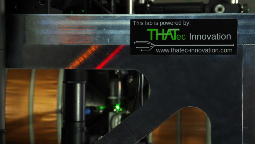
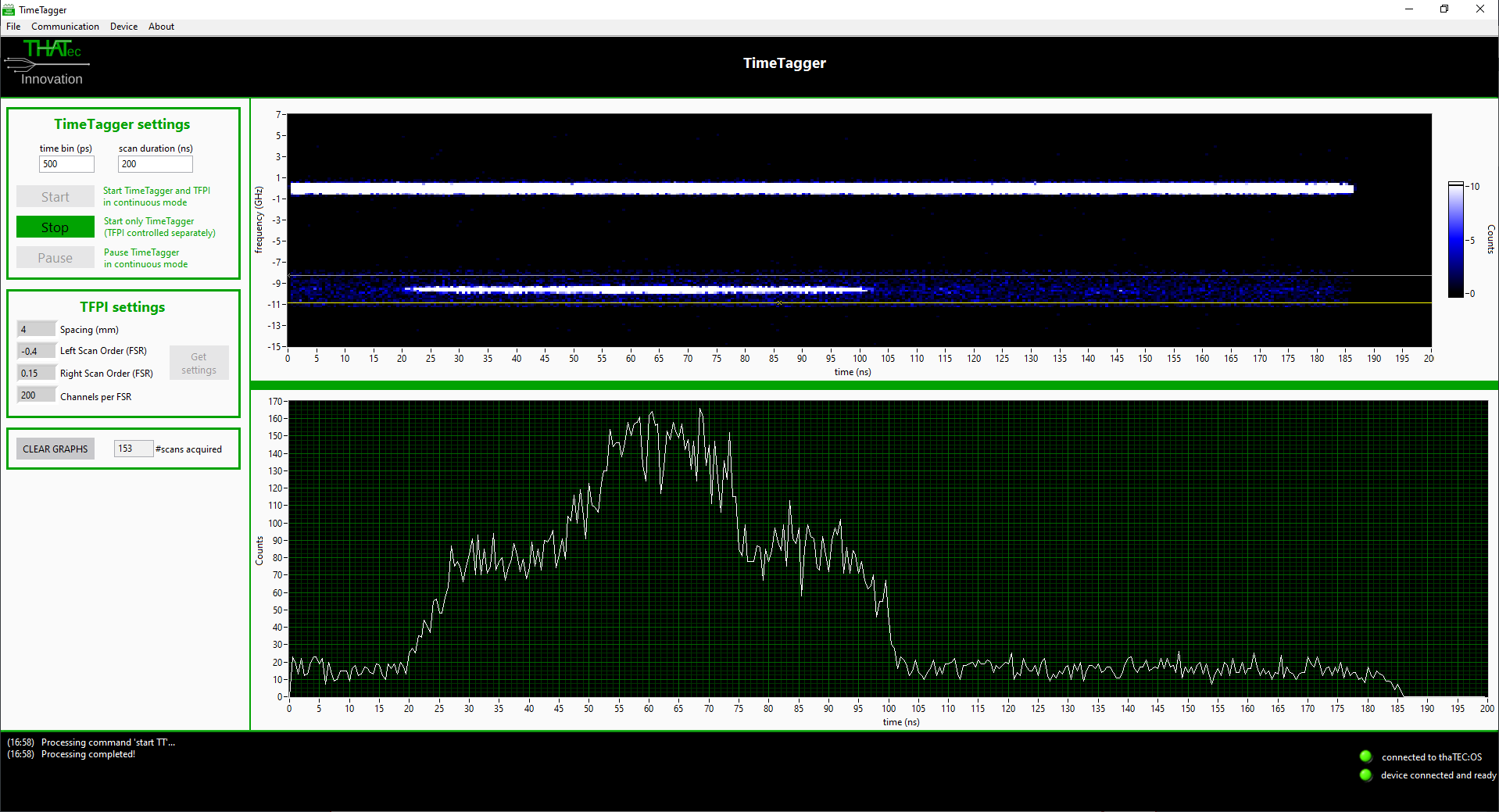
Important Note:
Even if the count rates (in particular for the stop channel/detector) match the expectations, a too low value might result in a wrong timing since some pulses might be detected earlier than others due to variations of the pulse shape. Thus, always check if the acquired signal matches the expectations. Below, the result for a 50 ns long pulsed excitation is shown with incorrect (left) and correct (right) trigger level settings displaying the effect on the acquired data.
Depending on the date of purchase of your license, your dongle has feature 19 or feature 21 activated for time-resolved Brillouin light scattering measurements using a Time Tagger from Swabian Instruments.
Thus, after downloading the software if a license error occurs on the first startup even though the USB donlge is present, you need to manually select the feature. To do so, select File => License setting from the menu bar and select Feature 19 or Feature 21 according to your license and restart the application.